Tuesday, March 29, 2016

Proportional Control

Last time we used Bang Bang Control this time we are doing the same thing but with Proportional Control!\
So what's the  difference?
Bang bang: Turns the on or off
Proportional: The farther you are from the goal the more you correct, the closer you are to the goal the less you correct so for proportional control power is proportional to error, and error=goal-reality.     Power=error x Kp where Kp = constant of proportionality or gain
The thing to keep in mind when using proportional is that is gain is too high it can overshoot the goal and if gain is too low it will never reach the goal.

Drive straighter
For our first code we found that nothing really helped make the SciBorg go straighter, so we tested the motors again and found that motor 1 is faster. So we switched the code to make (motor1-motor2)+rpms2 and lowered motor1's speed. Then we tried other Kp  values starting from -.01 which started pretty straight but eventually curved a lot until we got the right constant for us, which was
Kp =-1.

Different Surface Trials:
"Normal" (lab floor): goes straight
"High Friction" (Carpet): turns a little. Hypothesis: the added friction makes the car turn a little because any natural difference between power of the motors is hieghtened and also the ball has a harder time rolling onthe surface
"High Friction/Low Friction" (One wheel on carpet one wheel on flat sticker): it turns when the naturally faster motor is on high friction but not when the faster motor is on low friction. Hypothesis: high fric/low fric is basically a correction so with our added correction in the code it does not run straight.

Go 10 feet
We found the total position for 10 ft to be 12650 and then tried different Kp  values until we got the right one which was: .01
We found that this is not very accurate, as it would often stop around 3 inches away from the finish line. This is due to the "under shoot/overshoot" problem cause by the nature of proportional control and introducing gain.


Nudge: This function is used to make the "Drive 10 ft" more accurate by adding a little nudge when the Sciborg starts to slow to a halt. We did this by finding the position of the SciBorg when it slows to a halt with our laptop and adding another proportional control in "else" to make it nudge. Using this we got the SciBorg to land right on top of the line!

Ultrasonic Sensor:
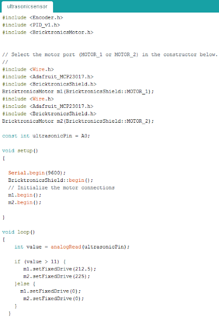
This task was pretty straightforward, because following another object is something proportional control is naturally good at doing, due to it's ability to gauge how much it needs to correct based off distance.

Follow the Line:
The biggest difficultly we had here was finding the perfect Kp for the SciBorg to move at the right angle.
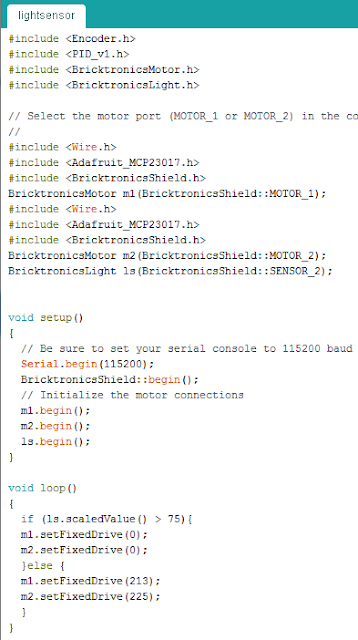
We found that proportional control was far more smoother and faster at following the line, which makes sense because Bang Bang was always on or off so it was very choppy.

Tuesday, March 15, 2016

Real World feedback and control

What are feedback and control?
Feedback and control are a combination of sensing, computation, and actuation.

1. Sensing: sensing a is very common feature of things in our world from photo cells, pressure sensors, even light switches have sensors!

2. Computation: computation is taking data from the sensor and doing things with it for example: the Arduinos we have been using in class.

3. Actuators: actuators are what does the task that the sensor perceives and the computer analyzes. Typically these are motors and pistons, but things such as light (as a part of the light switch system) can be considered an actuator.

Examples of systems of feedback and control:
1. Automatic sinks/water fountains/bathrooms
Sensing: A motion sensor tells the sink if a person is nearby
Computation: When there is motion sensed the computer tells the sink to release water
Actuation: A stream of pressurized water is released by a pump
Here's a video of an automatic sink/soap dispenser/dryer in Japan

3. Automatic doors: 
Sensing: A motion sensor tells the doors if a person is nearby
Computation: When there is motion sensed, the doors are told to move
Actuation: Motor moves the doors

Here's a video of a child's first reaction to automatic doors!
3. Self-Checkout machines
Sensing: A motion sensor tells the machine if a person is trying to checkout/scans products and coupons/weighs products on a scale to make sure it is the right product being sold
Computation: The checkout machines is a computer that compiles all of the data
Actuation: Screen displays options for the buyer
 

Friday, March 11, 2016

Sensors & Bang Bang Control

We continue where we left off: moving our SciBorgs around, but this time with sensors and bang bang control so we can maneuver the SciBorg more precisely.

Motor Encoder: This sketch enables us to see the exact position of the wheel with the serial print code. We observed that the motor position does not go back to zero despite the motor going forward for 1 second and backwards for 1 second. We concluded that this is because the forward and backwards motions are added up in separate lines of code and they are not equal because they are taking the real life position, we tested they out by forcibly making the motor stop with our hands. In real life there are many variables that cause the motors to behave differently, including the degradation of motors over time, friction and much more which accounts for the non-zero differences between the forward and backwards total readings.

When we tested moving 10 feet with the motor encoder we found out that is it not every consistent due to the wonky path of the SciBorg, it would vary from ending 6 inches away from the 10 ft mark to right on top.


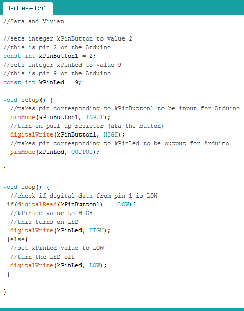
Touch Switch using this was very straightforward, although a good note to self is to always check what the code is printing in because we thought our circuit was somehow wrong because we were not using the right baud to read the print. We played with the delay a little because the 10 millisecond delay was printing out the input really fast, but concluded that 10 millisecond delay is probably the most effective.
When we tried the touch sensor on the car, it was very effective but not particularly useful because it had to be touching the surface.


Light Sensor: Using the light sensor was more tricky because there are a lot of shadows which are all dependent on the light source so it is challenging to get a perfect precise distance to put it at. We tested out the optimum reading for a white surface is around 90, for black surface 0, for brown surface around 30-40. The highest we have seen it read is 97, which we got by shining our phone light on the light sensor. When we put the sensor really close to a surface the numbers near 0.  We also tried putting on the LED which did not help at all, it instead made the range of inputs way smaller, almost reading the tan desk as 0. Finally after much trial and error we measured the ideal distance to be 1.5 cm


Ultrasonic Sensor: As Amy said in class, sonic sensors are not very precise forms of input when we tested it out we found that: 150= white noise, 11= 6 in, 17 ~10 in
Surprisingly when we tested out the sensor worked pretty well, although it was definitely not very precise because it did not stop at exactly where we wrote it to in the code.


Drive Straight: While driving straight seems like a very simple task this actually was one of the harder tasks for our group. Our SciBorg was very erratic, as things in real life often are, while we got a code in the end that runs pretty well on the lab floor it wouldn't work on the carpet because of the high friction. We were able top get the car down the wood ramp, but it had difficulty getting up due to the force of gravity. We tried our SciBorg on the ground by the Leaky Beaker too because it was difficult to find a high friction low friction floor that wouldn't interfere with the ball, the carpeted area by leaky beaker with a sticker on it was the most effective. This high friction and low friction combo made the car drive off the high friction surface.


Bang Bang follow the Line: This task was by far the most difficult, we first made a code that was supposed to simply follow the line, but this clearly would not work on this bending track we have, so instead we made a code that would move side to side sensing the white line. We eventually figured out that it would be easier to sense the sides between the line and the brown board than to sense just the pure white line. But then we couldn't get the car to move correctly so we tried ajusting the delay to no avail, then tried to write a code using no delay, but instead using the "if millis()" function, those all did not work. Finally we found out that our SciBorg was not only moving too fast but with turns too big. We found out that the magnitude of the "set fixed drive" controls speed and the difference of the two fixed drives control the angle and eventually we figured out the right speed and angle combination to make our SciBorg successfully followed the line!

Sunday, March 6, 2016

SciBorg fun!

This assignment was our first time working with SciBorgs!
Before our main tasks we were given a activity to introduce us to Arduino functions:

Then we got our hands on our very first SciBorg! And played around with the single motor program, then we got down to business with our tasks.
1. BothMotors: create a sketch that runs both the motors at the same time and speed.
This task was pretty straightforward, all we really had to do was just add the second motor by copying what was already there for the first motor.


2. Minimum Speed: Find the minimum speed that allows your SciBorg to move.
We first tried making the wheel move in the single motor program and found that the slowest speed for a wheel to move is 55, but when we put it in the BothMotor program and put it on the ground it didn't move. Realizing that getting the wheel to turn and getting the SciBorg to move are two different things we then tried setting it at 65, 60, 70 then finally 75 which we found to be the minimum speed for the SciBorg to move.


3. Hard Turn: Make a sketch for the SciBorg to make a hard turn
This was also a pretty straightforward task, we just did as instructed and put one motor full power forward and on motor full power reverse.


4. Soft Turn: Make a sketch for the SciBorg to make a gentler turn.
The first thing we tried was just making the speeds smaller, so we made both the speeds 150 and 150 which did give us a gentler turn.


But we wanted to test the limits of how gentle we could make this turn, so we tested out a bunch of other variables:
-Increasing delay: This just made the turn longer, so the angle of the turn was far more dramatic.


-Making the reverse speed smaller: (forward 150, reverse 75) When we did this the SciBorg didn't even move, we hypothesized that the differences between the speeds were to great so the turn would not work. We then tried setting forward 150, reverse 100: this time the SciBorg did turn, but only slightly and it was not consistent. We hypothesized that we need to set the speeds equal and so we had our next experiment:
-Setting both the speeds equal and slower: (forward 75, reverse 75) This also did not turn to our surprise. We concluded that turning requires a fairly high reverse speed.

<--Forward 150, Reverse 100


Forward 75, Reverse 75 ->


5. Does it measure up? Time how long it takes for the SciBorg to travel 10 ft. Write a sketch that makes the SciBorg travel for this much time and then stop. Why doesn't the SciBorg stop on the line?
Our SciBorg took 16 seconds to reach the 10 ft. So we altered the sketch by adding a "if(millis()<1600)" statement so that when the SciBorg has run for 16 seconds the SciBorg will stop (it's velocity will be zero). When we tested it out after this we found that the SciBorg stopped short of the finish line by 6 inches. Why? Well when we did our 10 ft tests the SciBorg actually started making curves despite the speeds for both motors being the same. We concluded that in real life two motors can never run at exactly the same speed. There are also many other variables like the flatness of the surface of the ground and the battery life that can effect the path of a SciBorg. which is why sensors in many ways are a more accurate way of getting a SciBorg to go exactly 10 ft.


Friday, March 4, 2016

Arduino Introduction 2

We were issued 3 more challenges to familiarize ourselves with Arduino, let's face it you can't resist(or) it.

1. Use the photocell to change something about LED behavior based on the room brightness. 
To do this we had to use the photocell and calibrate it to each specific resistor. We made one of out LEDs go on when it was light and then turn off when it was dark and vice versa. Learning how to use print was really helpful because it enables us to check if the senor and everything in the circuit was running well.
2. Use the tiny tactile switch to turn the LED on and off
This task was pretty straightforward, we just copied what the worksheet had said.

3. Use sweep and knob to control your servo, change knob so the servo only rotates between 60 -120 degrees. We figured out how to connect the circuit via google and played with the code to get it to go between 60-120 degrees. We also put an LED on it as a placemarker for the video.


Tuesday, March 1, 2016

Arudino Introduction

We started our first day working on Arudino! We had a few mini programming challenges to get us familiar with this open source education based electronics prototyping platform.

1. Blink with Delay of 10: this code made the "blink" action so fast that human eyes can not see it. This shows the remarkable speed at which the Arudino works at.


2. Pattern at least 3 LEDs of different colors using the delay function


3. Use the potentiometer to change something in the LED behavior
This was actually more challenging than it seemed to arrange all of the parts on the breadboard because adding the potentiometer required adding more wires compared to just the LEDs.


4.Pattern with at least 3 LEDs of different colors that does not use the delay() function